-
Single layer tile press series
-
Double layer tile press series
-
Three layer tile press series
-
Floor bearing plate equipment
-
Glazed tile equipment series
-
Jiaochi equipment series
-
C/z/u-shaped steel forming mac
-
Carriage plate forming machine
-
Anti skid embossing equipment
-
Aluminum magnesium manganese 4
-
Ridge tile forming machine ser
-
Light steel keel machine serie
-
Shearing machine bending machi
-
Rock wool foam integrated sand
-
Rolling shutter door equipment
-
Discharge rack series of hydra
-
Export equipment series
-
Kaiping machine series
-
pipe benders
-
Customize cold bending equipme
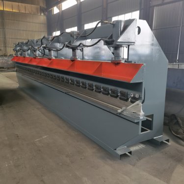
Hydraulic bending machine

Hydraulic bending machine is a machine that can bend thin plates. Its structure mainly includes support, workbench and clamping plate. The workbench is placed on the support. The workbench is composed of base and pressing plate. The base is connected with the clamping plate through hinges. The base is composed of base shell, coil and cover plate. The coil is placed in the depression of the base shell, and the top of the depression is covered with cover plate. When in use, the coil is powered on by the wire, and after being powered on, it generates gravity on the pressing plate, so as to realize the clamping of the thin plate between the pressing plate and the base. Because of the electromagnetic force clamping, the pressing plate can be made into a variety of workpiece requirements, and the workpiece with side wall can be processed, and the operation is also simple
the hydraulic bending machine includes a support, a workbench and a clamping plate. The workbench is placed on the support. The workbench is composed of a base and a pressing plate. The base is connected with the clamping plate through a hinge. The base is composed of a base shell, a coil and a cover plate. The coil is placed in the depression of the base shell, and the top of the depression is covered with a cover plate
when in use, the coil is powered on by the wire, which generates gravity on the pressing plate, so as to realize the clamping of the thin plate between the pressing plate and the base. Because of the electromagnetic force clamping, the pressing plate can be made into a variety of workpiece requirements, and the workpiece with side wall can be processed. The bending machine can meet the needs of various workpieces by replacing the bending machine mold
hydraulic bending machine is divided into manual bending machine, hydraulic bending machine and numerical control bending machine. The manual bending machine is divided into mechanical manual bending machine and electric manual bending machine. The hydraulic bending machine can be divided into: torsional shaft synchronization, mechanical hydraulic synchronization, and electrical hydraulic synchronization according to the synchronization mode. According to the movement mode, the hydraulic bending machine can be divided into: up moving type and down moving type
hydraulic bending machine is an important equipment for workpiece bending and forming in the sheet metal industry. Its function is to press the steel plate into parts of various shapes according to the process needs. As shown in the figure is the structural diagram of the hydraulic sheet metal bending machine, which is mainly composed of left and right columns, worktables and beams. The left and right oil cylinders are fixed on the columns, the slider is connected with the piston of the oil cylinder, and moves up and down along the guide rail fixed on the columns. The lower mold is fixed on the worktable, and the upper mold is installed at the lower end of the slider. The hydraulic system provides power, and the electrical system gives instructions. Under the action of the oil cylinder, The slider drives the upper die downward to close with the lower die to realize the bending of the sheet metal. The left and right columns, worktables and sliders (hereinafter referred to as the three major parts) are the key parts of the bending machine, and the sum of the weight of the three major parts accounts for 70% - 80% of the total weight of a bending machine. Its strength and rigidity directly determine the running accuracy, service life of the machine tool and the accuracy of the workpiece
1. Slider part: hydraulic transmission is adopted, and the slider part is composed of slider, oil cylinder and mechanical stop fine-tuning structure. The left and right oil cylinders are fixed on the frame, the piston (rod) drives the sliding block up and down through hydraulic pressure, and the mechanical stop is controlled and adjusted by the numerical control system
2. Workbench part: operated by the button box, the motor drives the stopper frame to move forward and backward, and the moving distance is controlled by the numerical control system. Its small reading is 0.01 mm (there are travel switch limits at the front and rear positions)
3. Synchronization system: the machine is a mechanical synchronization mechanism composed of torsion shaft, swing arm, joint bearing, etc., with simple structure and stable performance. The mechanical stop is adjusted by the motor, and the numerical control system controls the value
4. Material retaining mechanism: the material retaining adopts motor drive, drives the two screw rods to move synchronously through chain operation, and the numerical control system controls the size of the material retaining
